
Integer Frequency Divider 14GHz – Obsolete
Model G1142
- Wide frequency range up-to 14GHz
- Continuous division ratios from 1 to 256
- 50% duty cycle of the output divided clock signal
Integer Frequency Divider
Programmable integer clock divider is working with input signal frequencies up-to 14GHz and has static adjustment of the 1-256 division ratio through 8-bit front-panel dip-switches or via an optional rear-panel accessible mini-B USB connector. The low phase noise and jitter of the divider is critical for applications requiring precise synchronization between device clocks. The functional block diagram of the device is shown in Figure 1.
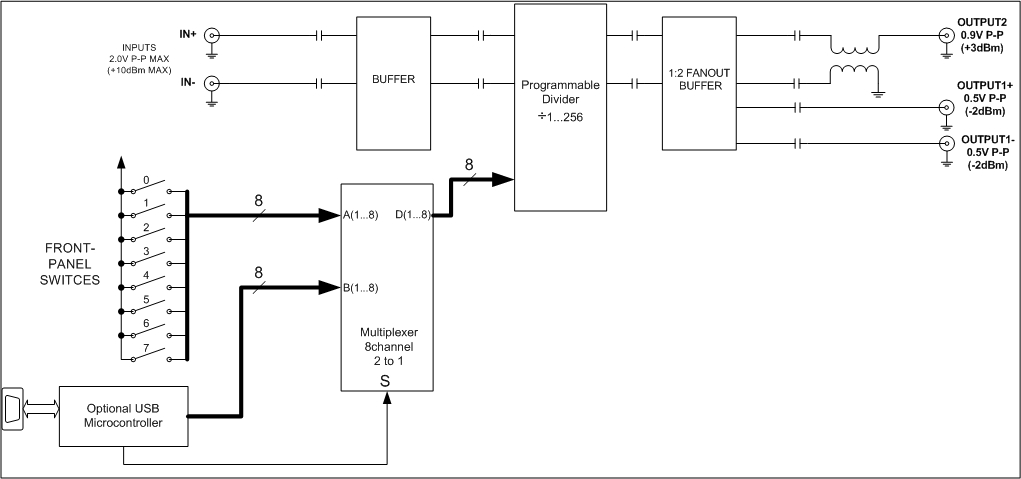
Figure 1. Integer Frequency Divider Block Diagram
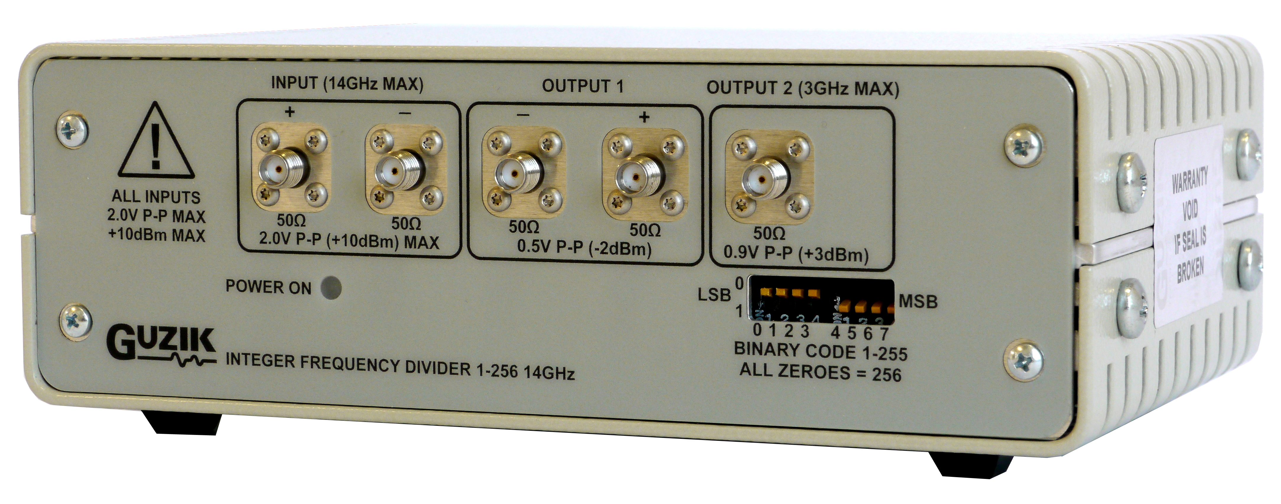
The divider accepts an input clock signal via +INPUT/-INPUT and provides a clean 50% duty cycle output divided clock signal to differential +OUTPUT1/-OUTPUT1 with maximum specified frequency or single-ended OUTPUT2 with maximum output frequency of 3GHz in any operational mode. Unused inputs and outputs should be terminated to 50Ohm. The divider allows for static adjustment of the division ratio from 1 to 256 with a step of 1. The binary code on the front-panel dip-switch control 0-7 defines the value of the ratio from 1 to 255, where 7 is the most significant bit. All “0”s (“low” state) defines the division by 256.
Specifications*
Input
- Level: -6dBm to +10dBm, (300mV to 2.0V P-P) single ended.
- Impedance: 50 Ohm single ended or 100 Ohm differential.
- Return loss: -8dB @ 10GHz
Output
Differential OUTPUT1:
- Level: 1V P-P or 0.5V P-P single ended.
- Impedance: 50 Ohm single ended or 100 Ohm differential.
- Return loss: -15dB @ 10GHz OUTPUT1
- Single ended OUTPUT2:
- Level: 0.9V P-P single ended.
- Impedance: 50 Ohm.
- Return loss: -15dB @ 3GHz OUTPUT2
Typical Phase Noise**:
- 14GHz input, division ratio 1: -110dBc @ 100kHz offset
- 14GHz input, division ratio 14: -120dBc @ 100kHz offset
Electrical/Mechanical Specifications
- Form Factor: 4.88”x7.13”x2.35”
- Front Panel: 2 INPUT SMA female connectors, 2 OUTPUT1 SMA female connectors, 1 OUTPUT2 SMA female connector, 0-7 dip-switches
- Rear Panel: +12V DC IN 2.0A, Optional mini-B USB connector.
- Front Panel Indicator: POWER ON GREEN LED
- Rear Panel Indicator: POWER ON GREEN LED
Operating Environment
- Temperature Range: 0° to 50°C (32° to 122°F)
- Relative Humidity: 10 to 90% non-condensing
- Designed to meet UL 60950, FCC Class B, CE safety and emissions
Ordering Information
Please contact sales@www.guzik.com to obtain a quotation for the S60-706777-XX INTEGER FREQUENCY DIVIDER.
*Specifications are subject to change without notice.
**The phase noise increases for low slew rate input signals.
It is recommended to use input signal with fast rise/fall time for low frequency operations.