
RWA DTR 3000 Series – Discontinued
- Base models are capable of 2Gbit/sec, 3Gbit/sec, and 4Gbit/sec
- Provide tests and measurements of both DTR and non-DTR components (heads and disk drive media)
- DTR 3000 Series can work with both Guzik and non-Guzik spinstands
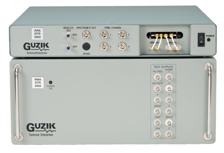
The Read Write Analyzers of DTR 3000 series – the RWA DTR 3002, 3003, and 3004 – function at breakthrough speeds. The base models are capable of 2Gbit/sec, 3Gbit/sec, and 4Gbit/sec, respectively when connected to the latest UP10M preamplifier and MR7 head amplifier.
As a part of DTR 3000 test system, these Read Write Analyzers provide tests and measurements of both DTR and non-DTR components (heads and disk drive media). These Read Write Analyzers support both Drive Servo decoding and Guzik Servo decoding.
Other options include: PRML chip adapters, programmable filters, programmable differentiators, and various software modules.
The DTR 3000 Series can work with both Guzik and non-Guzik spinstands.
| RWA Model | Maximum Data Rate | Maximum Analog Bandwidth |
| RWA DTR 3002 | 2Gbit/sec | 1.0GHz |
| RWA DTR 3003 | 3Gbit/sec | 1.5GHz |
| RWA DTR 3004 | 4Gbit/sec | 2.0GHz |