
WDM5000 Series Waveform Digitizers – Obsolete
- High Speed Waveform Digitizers with up to 10, 20, or 40 Gs/sec sampling rate.
- Analog bandwidth of either 4, 8, or 12.5 GHz1.
- Industry leading waveform memory per channel of up to 4 Gpoints.
- FPGA-based reconfigurable digital signal processing module with up to 5 GS/sec processing speed for high-throughput for production test applications.
- Advanced measurement suite including FFT, Eye Diagram and Jitter analysis.
- Up to 100 MB/s fast transfer rate from WDM 5000 Series system to external computer using PCI Express connection.
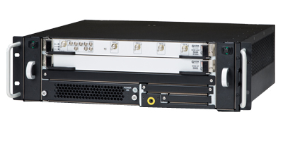
- Upgradeable architecture based on industry standard Advanced TCA2 form factor with convenient front-panel interconnection.
Waveform Digitizers
The Guzik WDM 5000 Waveform Digitizer family provides high-speed waveform capture and parametric analysis capabilities for disk drive head and media testing as well as high-speed transient waveform capture. Unlike conventional oscilloscopes or waveform digitizers, the WDM 5000’s architecture was built to provide ultra-long waveform memory and the highest measurement throughput for capturing and processing single shot data or testing on the factory floor. The 12.5 GHz analog bandwidth combined with 40 GSa/s sampling rate and ultra long waveform capture memory provides the capability to capture the most demanding signals.
The WDM5000 Waveform Digitizers provide the world’s longest waveform capture time window. At the maximum speed of 40 GSa/s and using all 4 Gpoints of storage, 100 msec of waveform data can be captured and stored for further analysis. In addition, the WDM 5000 Series utilizes a high-speed hardware-based Digital Data Processor with speeds up to 5 GSa/s (for parametric measurements). The product can execute customer-defined complex measurement algorithms, and it does it almost 100 times faster than digital oscilloscopes currently available on the market. The WDM 5000 architecture, built on the industry-standard Advanced TCA platform, allows customers to protect their system investment by allowing for future component upgrades.
The WDM 5000 Signal Explorer Control and Interface software is included as a standard accessory with each WDM 5000 Waveform Digitizer unit. This software allows stand-alone operation of the WDM 5000 digitizer with a host computer. (The host computer must have an open PCI Express x1 slot to house the Guzik PCIe x1 Bridge Card or an approved PCIe x1 Express Card, such as the One Stop Systems OSS-PCIe-HIB2-EC-x1 Express Card.) The WDM 5000 connects to the host computer via aPCIe x1 cable, and the Signal Explorer software provides a real time oscilloscope-like user interface.
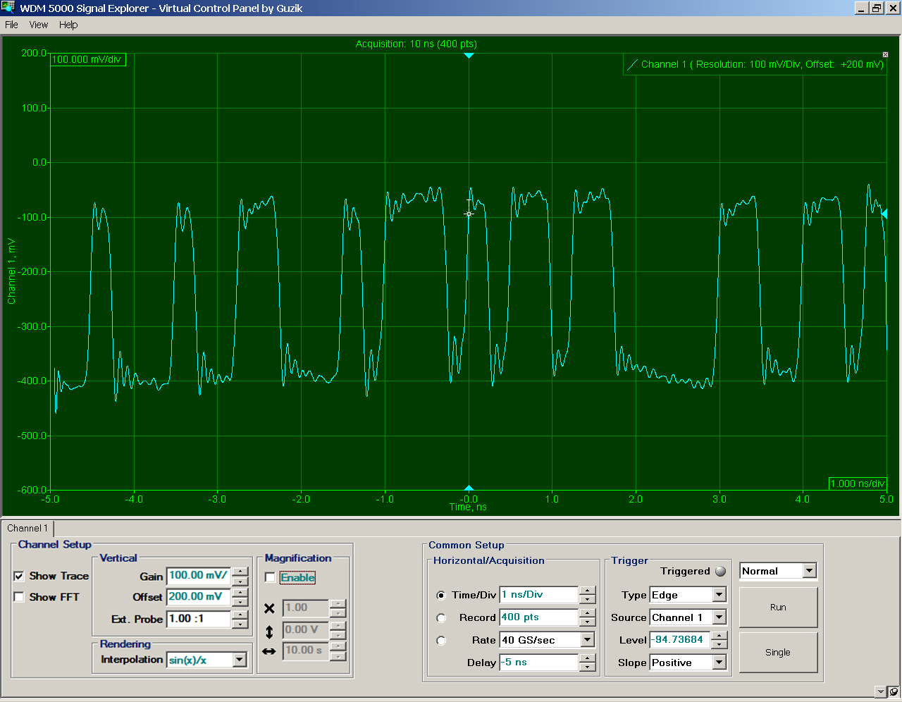
Click here to view the detailed JPG file of this screen shot.
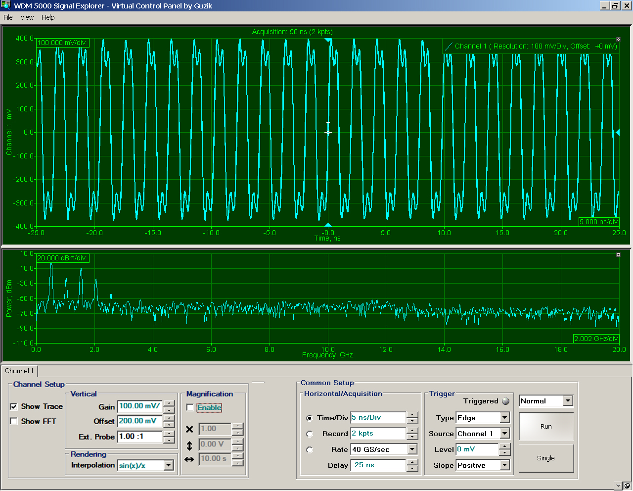
Waveform data is updated in real-time, so the user experience is similar to using a modern PC-based oscilloscope. Channel Tabs will appear for each channel provided by the particular WDM 5000 model being used. Controls are arranged at the bottom of the screen in a familiar and easy to navigate panel, and waveform data appears above. In addition to channel data, the FFT of any channel can be displayed as well. Since FFT’s are being processed in hardware, the display update is extremely fast. Measurement cursors, waveform zoom, and a variety of other visual measurement tools are provided to make operation quick and easy.
| Model | Bandwidth | Sample Rate | Channels | Memory / Channel |
| WDM 5121 | 12.5 GHz | 40 GSa/s | 1 | 4 GB |
| WDM 5082 | 8 GHz | 20 GSa/s | 2 | 2 GB |
| WDM 5044* |
4 GHz 4 GHz |
10 GSa/s 20 GSa/s |
4 2 |
1 GB 2 GB |
________________
* The WDM5044 is capable of operating in 2 modes – 10GS/sec on 4 channels or 20GS/sec on 2 channels.
WDM 5000 Series Block Diagram
The Guzik WDM 5000 Waveform Digitizers incorporate the following building blocks:
- WDM ADC 10, 20, 40 Gs/sec Data Acquisition Module with 4 Gbyte built-in memory
- WDM DP 5002 high-speed Digital Data Processor
- Two WDM RTM boards (Rear Transition Modules) to provide PCI-Express interface and power
- Modular industry-standard ATCA 2 Slot/3U chassis enclosure
System Configurations
WDM 5121: Guzik WDM 5121 Waveform Digitizer System provides parametric analysis capabilities specially optimized for production test applications consisting of:
- Data Acquisition Module WDM ADC 5121
- Digital Data Processor WDM DP 5002
- Two ATCA RTM Modules WDM RTM-A and WDM RTM-B
- Industry-Standard ATCA Chassis
WDM 5082: Guzik WDM 5082 Waveform Digitizer System provides parametric analysis capabilities specially optimized for production test applications consisting of:
- Data Acquisition Module WDM ADC 5082
- Digital Data Processor WDM DP 5002
- Two ATCA RTM Modules WDM RTM-A and WDM RTM-B
- Industry-Standard ATCA Chassis
WDM 5044: Guzik WDM5044 Waveform Digitizer System provides parametric analysis capabilities specially optimized for production test applications consisting of:
- Data Acquisition Module WDM ADC 5044
- Digital Data Processor WDM DP 5002
- Two ATCA RTM Modules WDM RTM-A and WDM RTM-B
- Industry-Standard ATCA Chassis
System Components
ADC 5121 Data Acquisition Module:
- 1 channel with 40 GS/sec sampling rate
- 5 GHz analog bandwidth
- 8-bit resolution
- 160 Gbit/sec data interface to backplane
- 4 Gbyte Memory
ADC 5082 Data Acquisition Module:
- 2 channels with 20 GS/sec sampling rate per channel
- 8 GHz analog bandwidth
- 8-bit resolution
- 160 Gbit/sec data interface to backplane
- 4 Gbyte Memory
ADC 5044 Data Acquisition Module:
- 4 channels with 10 GS/sec sampling rate per channel or 2 channels with 20 GS/sec sampling rate per channel
- 4 GHz analog bandwidth
- 8-bit resolution
- 160 Gbit/sec data interface to backplane
- 4 Gbyte Memory
DP 5002 Digital Data Processor:
- Up to 5 GS/sec Data processing speed
- 80 Gbit/sec data interface to backplane
RTM-A Module:
- 1X PCI-Express interface to PC
- 200 Watt power supply for Data Acquisition Module
RTM-B Module:
- 200 Watt power supply for Digital Data Processor Module
Chassis:
- 3U 19″ rack mountable AdvancedTCA shelf
- Two AdvancedTCA slots
- 15X replicated mesh backplane
- 800W Universal Power Supply
WDM 5000 Series Physical Specifications
- Chassis type: Standard 3U ATCA Chassis
- Dimensions (H x W x D): 131 mm X 441.8 mm X 416.5 mm (5.16” X 17.39” X 16.40”)
- Weight: 15.9 kg (35 lbs)
- Line Power Consumption: 110 VAC (± 10%, 50/60 Hz, 2.5A approximately) 230 VAC (± 10%, 50/60 Hz, 1.2A approximately)
WDM ADC Data Acquisition Modules
Key Specifications
- Up to 4 channels
- Up to 40GS/sec sampling rate
- 4, 8, or 12.5 GHz analog bandwidth
- 8 Bit resolution
- 4 Gbyte built-in memory
- Nonlinear distortions < 0.2% at 200 MHz, < 0.5% at 2.4, 8, 12.5 GHz
- High speed data interface 160 Gbit/sec to back plane
WDM DP 5002 Digital Data Processor
Key Specifications
- Eye diagram and jitter analysis with unique capabilities to separate and measure different jitter components (head related jitter, media related jitter, pattern related jitter)
- Fast Fourier Transform (FFT) for frequency-domain analysis
- Universal Viterbi detector is able to perform Variable Target decoding and work with both longitudinal and perpendicular recording
- Digital filtering, digital equalizing, digital clock recovery
- 80 Gbit/sec interconnection to back plane
- Up to 5 Gs/sec data processing speed
- Parametric measurements based on average pulse profile with 1% measurement accuracy down to 12 dB SNR
- Possibility to load custom-designed decoding algorithms
WDM 5000 Series Integration with Guzik Test System for Disk Drive Test
The WDM 5000 Series can be integrated into the Guzik Test System based on RWA DTR 3000 series or RWA-2000 Series. This option adds a digital measurement capability to the existing system. The picture below shows the system with WDM 5044, RWA DTR 3002, and DTR 3000 spinstand. The WDM 5000 Series integrates in WITE32 engineering and production environment.
Host Computer Connection
The WDM 5000 Series connects to the same host computer, which runs WITE32 software controlling Read Write Analyzer and a Spinstand. The control over WDM 5000 Series is provided by the host computer via 1x PCI-Express link, which delivers up to 100 Mbyte/s sustainable data transfer rates. The PCI-Express link consists of PCI-Express 1x host adapter computer card that is connected via PCI-Express cable to the RTM module of the ATCA chassis.
- RWA DTR 3000 Series or RWA 2000 Series
- Guzik Spinstand DTR 3000, Guzik Spinstand V2002, or Canon Spinstand
- WITE32 Revision 4.10 or greater
- One spare PCI-Express slot in the host PC to accommodate additional
PCI-Express Bridge card
________________
1 All specifications are subject to change without notice
2 Advanced TCA and ATCA are registered trademarks of PICMG (PCI Industrial Computer Manufacturers Group)
Please contact sales@www.guzik.com to obtain a quotation.