
D5000 Digital Media Scanning
- Transition time shift (bit shift) and amplitude analysis
- Various defect detectors for simultaneous analysis of bit shift, missing pulses, super pulses, and thermal asperities
- Multi-threshold amplitude analysis at positive and negative signal peaks
- 24 detectors can run in parallel with different settings/thresholds
- Time shift (bit shift) analysis by zero-crossing detection
for perpendicular recording - High sampling rate for precise reconstruction of read-back signal
- High resolution of detection thresholds
- Real-time digital processing for high throughput
- 3D presentation of media defects
- Field upgradeable processing algorithms
Introduction
D5000 Signal Analyzer opens new possibilities for media scanning. The analyzer can measure the amplitude defects (such as missing pulses, super pulses, and thermal asperities), and the time defects (such as transition shift). Up to 24 defect detectors can run simultaneously, with different settings. The high-resolution thresholds of the defect detectors and multi-threshold amplitude analysis allow the digital media scanner to generate three-dimensional map of the defects.
Scanning Algorithm
The typical signal used for media scanning is an HF pattern. This signal is read back as a high-frequency sine-wave signal. The read-back signal, digitized with high oversampling, controls digital PLL, which is running on frequency two times higher than the read-back signal. The phase of the PLL signal is adjusted such a way that each sample presents the positive and negative peaks of the read-back signal. The value of these samples allows you to analyze the amplitude defects on media. The position of zero-crossings of the read-back signal with respect to the PLL clocks (in case of perpendicular recording) presents a time shift (bit shift). The distribution of the zero-crossings is analyzed and qualified with respect to a detection window.
The scanning algorithm is implemented within the DP5000 Digital Processor. This algorithm can be updated, when you install a new revision of WITE32.
The DP5000 processor has the throughput high enough to process the signal from media without any delay, and then transfer all detected errors to the computer with high speed. High sampling rate and analog bandwidth allows D5000 Signal Analyzer to process a sine-wave signal with frequency up to 1.25GHz.
Table 1 shows the defects, which can be detected with the D5000 Digital Media Scanning.
| Defect | Read-back Waveform | Detector Type |
| Missing pulse or short group of missing pulses | 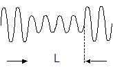 |
Missing Pulse |
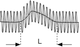
| Super pulse or short group of super pulses | 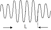 |
Super Pulse |
| Modulation: small amplitude | 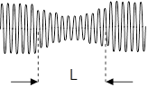 |
Missing Pulse |
| Modulation: large amplitude | 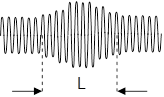 |
Super Pulse |
| Thermal asperity
(Baseline shift) |
 |
Thermal Asperity |
| Amplitude asymmetry | 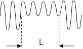 |
Thermal Asperity |
| Time shift | 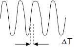 |
Time Shift |
Table 1: Samples of Detected Media Defects
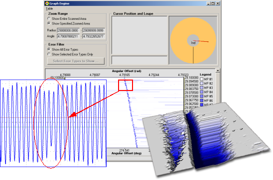
Figure 1 shows the disk area with a defect in the coordinates of track numbers and an angular head position with respect to the index. Different color shades correspond to different depth of the defect.
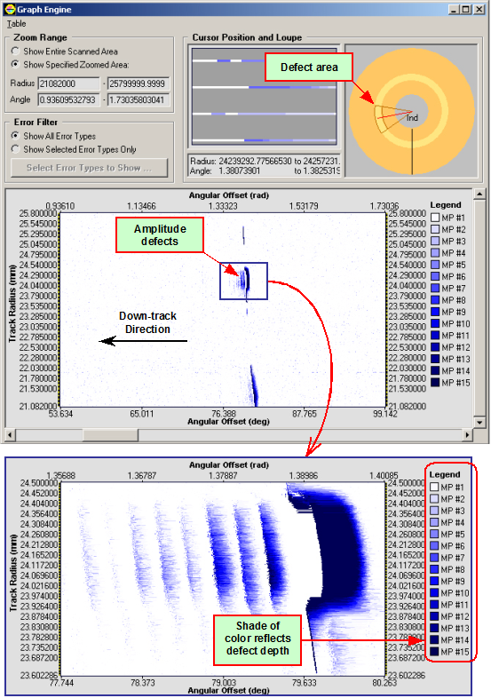
Figure 1: Amplitude Defects Detected on Media
The D5000 Digital Media Scanning includes 3D Viewer, which generates
the three-dimensional map of a found defect. Figure 2 shows such map created for
the zoomed-in area of the amplitude defect from Figure1.
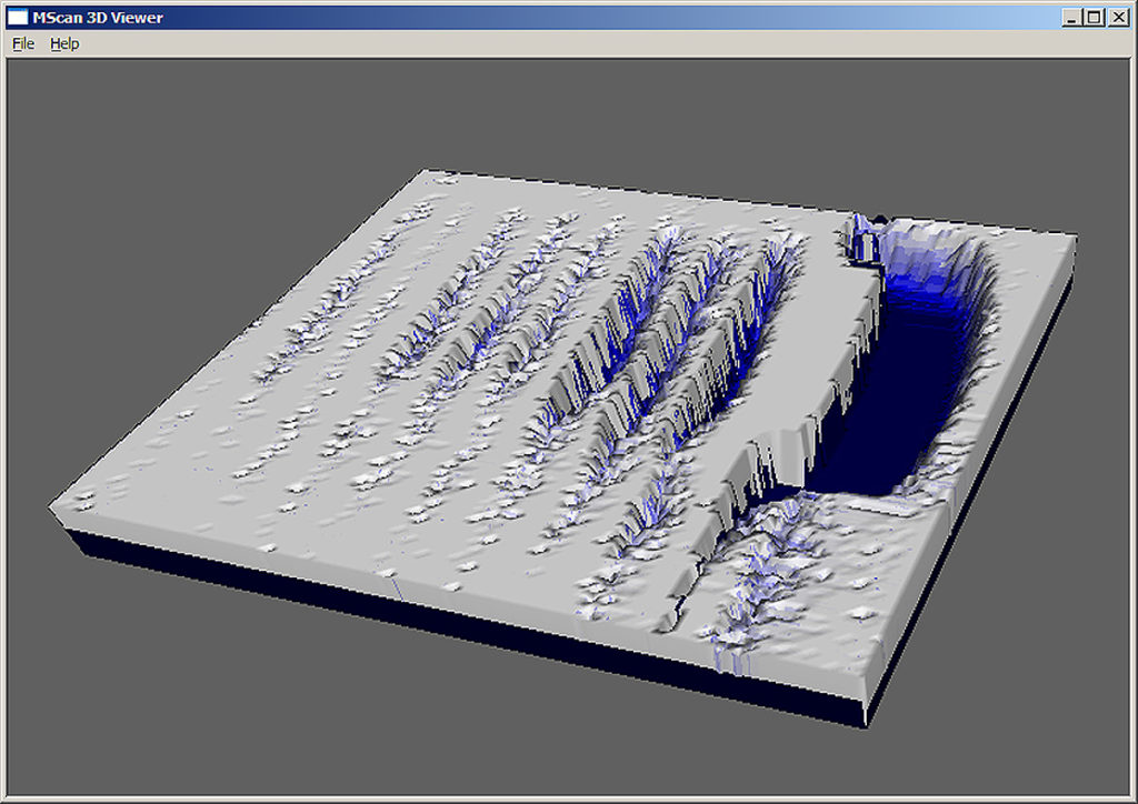
Figure 2: 3D Map of Amplitude Defect
Figure 3 shows the time-shift distribution (bit-shift plot) of the scan area.
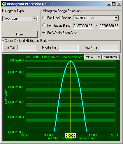
Figure 3: Bit-shift Plot
- Guzik D5000 Signal Analyzer
- Guzik RWA-2000 series
- Guzik V2002 or Canon spinstand
- WITE32 Revision 3.40 or later
- D5000 Digital Media Scanning license. Please contact sales@www.guzik.com to obtain a quotation for the license.