
DTR 3000 System
Test System for Discrete Track Recording (DTR)
- Digital Decoder
for Drive Servo with Programmable Parameters - Amplitude and Phase Servo Decoding
- Servo Signal Analog bandwidth up to 250 MHz1
- Automatic Media Centering Mechanism2 to Mechanically Align Media to Reduce Track Eccentricity below 800 nm within 20–30 seconds (typical)
- Servo Closed Loop – track following with residual RRO better than 5-7 nm3
- High-bandwidth Servo Loop with typical 0.2–0.6 nm NRRO3, 1s
- Full Range of WITE32 Tests, including Parametric, 747, ATI, BER, etc
- Digital Media Scan Test (Digital MSCAN)4
- Full compatibility with existing custom WDK modules
- System Supports both DTR Media and Conventional Continuous Media
- System Supports both Drive Servo and Guzik Servo
Every component of the DTR Test System has been redesigned from the ground up to provide the critical measurement capability to address the emerging need for the Discrete Track Recording measurements.
The system features up to 4 GBit/s write channel, up to 12 GHz read channel connected to 40 GS/s waveform digitizer, highly stable spinstand platform designed for recording densities beyond 700kTPI, and the state of the art programmable drive servo decoder for DTR servo decoding.
________________
1 All specifications are subject to change without notice
2 US Patent Pending
3 Performance may depend on the actual product (head and media combination)
4 Optional test module

Complete System Solution
DTR System Block DiagramMeasurement requirements are complex for this new emerging technology, Guzik has fully integrated all required system components to provide a complete test system ensuring the fastest time to market possible.
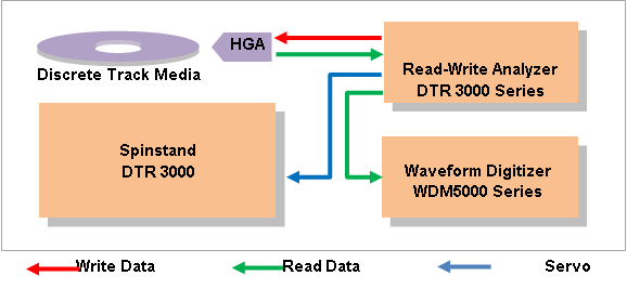
Figure 1. DTR System Block Diagram
The Guzik DTR Test System is a bundle of all critical components required for DTR test. These components include:
- RWA DTR 3000 Series Read-Write Analyzer.
- Spinstand DTR 3000 with Media Centering Mechanism and Piezo Actuator Cartridge.
- WDM5000 Series Waveform Digitizer.
RWA DTR 3000 Series
The new generation of Guzik Read-Write Analyzers includes the RWA DTR 3002, RWA DTR 3003, and RWA DTR 3004. These analyzers feature dual servo channel, capable of decoding both Guzik Servo and Drive Servo.
Servo decoding is performed by programmable digital decoder. You choose between Amplitude Servo mode and Phase Servo mode. You can also specify parameters of the servo pattern, such as clock frequency, preamble length, number and configuration of the servo bursts, etc.
The decoder is not based on a PRML chip; it uses the programmable digital signal processor instead. This provides media design teams with the flexibility to experiment with various configurations of servo patterns without waiting for a new revision of the PRML chip.
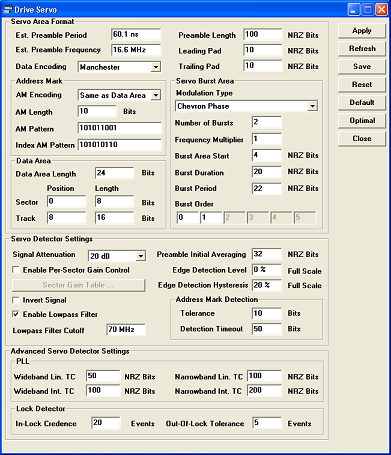
Figure 2. Drive Servo Configuration in WITE32
Three types of burst modulation are fully supported and tested with DTR media:
- Regular Amplitude (2-6 bursts)
- Phase-Change Amplitude (2 bursts)
- Chevron Phase (2 bursts)
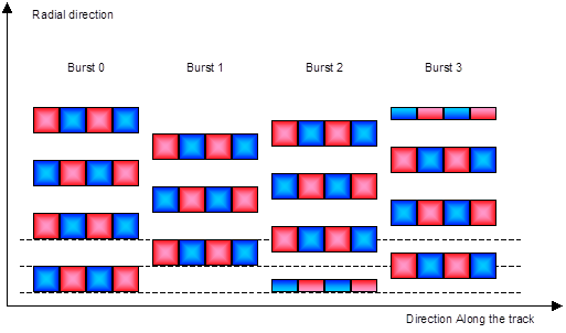 Figure 3. Regular Amplitude servo burst pattern
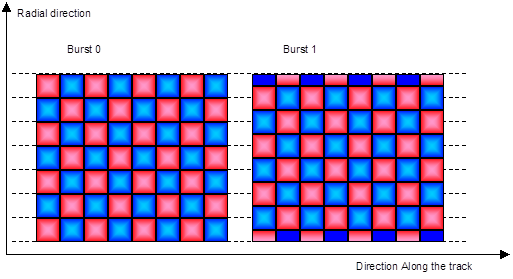 Figure 4. Phase-change Amplitude servo burst pattern
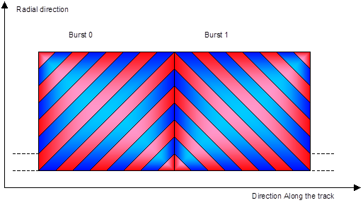 Figure 5. Chevron Phase servo burst pattern
Three encoding schemes of Track ID / Sector ID are supported:
- Binary (no encoding)
- Manchester
- Rate 2/4
| Binary: | ||||||||||
| 0 -> 0 | 0 | 0 | ||||||||
| 1 -> 1 | 1 | 1 | ||||||||
| Manchester: | ||||||||||
| 01->0 | 0 | 1 | 0 | |||||||
| 10->1 | 1 | 0 | 1 | |||||||
| Rate 2/4: | ||||||||||
| 0110 -> 00 | 0 | 1 | 1 | 0 | 0 | 0 | ||||
| 0011 -> 01 | 0 | 0 | 1 | 1 | 0 | 1 | ||||
| 1100 -> 10 | 1 | 1 | 0 | 0 | 1 | 0 | ||||
| 1001 -> 11 | 1 | 0 | 0 | 1 | 1 | 1 | ||||
| Encoded (Media Bits) |
Decoded (User Bits) |
|||||||||
Spinstand DTR 3000
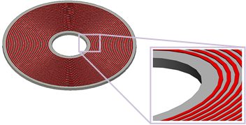
Guzik spinstand model DTR 3000 includes a media centering mechanism. When a media with pre-printed servo information is mounted on a spinstand, the servo and data tracks will have eccentricity up to 50–100 micro-meters in respect to the spin axis.
The media centering mechanism of the DTR 3000 spinstand mechanically aligns the disk to reduce track eccentricity below 800nm. The process is completely automated and typically takes less than 30 seconds.
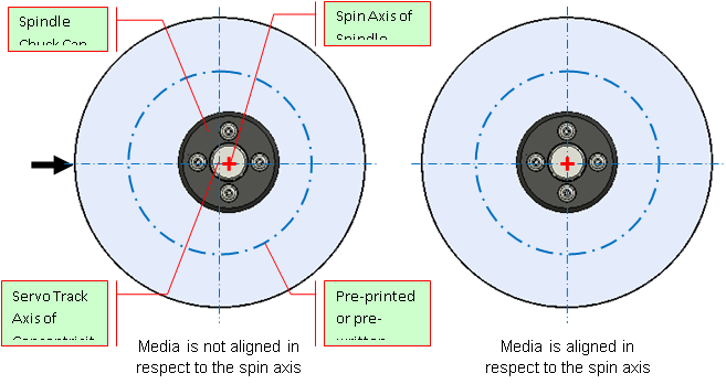 Figure 6. Centering of the Media to Reduce Track Eccentricity
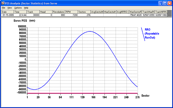
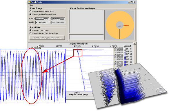
Figure 7. Track Eccentricity before Media Alignment (RRO 80,000 nm)
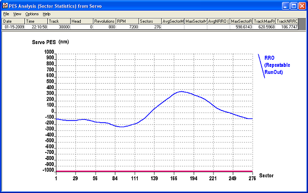
Figure 8. Track Eccentricity after Media Alignment (RRO 350 nm)
The piezo actuator cartridge further reduces the repeatable run-out below 5-7 nm using high bandwidth servo loop combined with servo feed-forward approach.
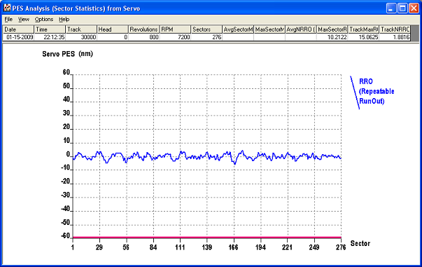
Figure 9. Track Eccentricity in Track Follow Mode with Servo Loop Closed (RRO 5 nm)
The combination of precision track centering, high stability air bearing spindle, and high bandwidth servo loop are the crucial components that allow for high-TPI DTR testing using Guzik Spinstand DTR 3000.
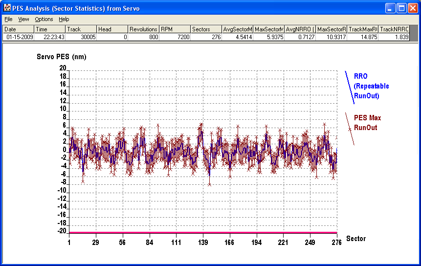
Figure 10. Position Error Signal (PES)
WDM5000 Series
The Waveform Digitizer WDM5000 Series is a high-speed digitizer with sampling rates up to 10‑40 GSample/s. The WDM5000 Series is a successor of the previous generation Digital Signal Analyzer D5000.
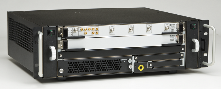
Figure 11. Waveform Digitizer WDM5000 Series
The Waveform Digitizer WDM5000 Series is a critical component of the complete DTR Test System, which provides the following key features not available with a traditional peak detector approach:
- Accurate digital measurements with 1% accuracy for heads with signal-to-noise ratio down to 12dB
- Digital media scanning (Digital MSCAN Test, optional purchase)
- Testing of servo area
- Jitter and Eye Diagram measurements
- Nano-scale magnetic field imaging (3D Pulse Profile Test)
- Capturing read-back signal waveforms around the defect area
The Waveform Digitizer WDM5000 Series consists of three models:
| Model | Bandwidth | Sample Rate | Channels | Memory / Channel |
| WDM 5121 | 12.5 GHz | 40 GS/s | 1 | 4 GB |
| WDM 5082 | 8 GHz | 20 GS/s | 2 | 2 GB |
| WDM 5044* |
4 GHz 4 GHz |
10 GS/s 20 GS/s |
4 2 |
1 GB 2 GB |
* The WDM5044 is capable of operating in 2 modes – 10GS/sec on 4 channels or 20GS/sec on 2 channels.
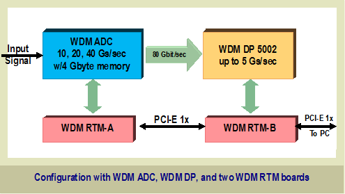
The figure below shows the block diagram of the Waveform Digitizer WDM 5000 Series:
The software for WDM 5000 Series includes the following tests and measurements:
- Digital Parametric Measurements
- Digital Media Scanning
- Jitter and Eye Diagram Measurements
- 3D Pulse Profile Test for Magnetic Field Imaging
- Fast Spectral Measurements
Figure 12. Digital Media Scan Test (MSCAN)
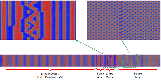
Figure 13. Magnetic Field Image of Servo Area Captured with WDM5000 Series
DTR Software Modules and Tests
In addition to the full range of standard WITE32 tests, Guzik offers the following tests specifically designed for DTR application:
- Media Alignment Test
- Servo Distortion Test
- Servo Track Pitch Calibration Test
- Servo Burst Amplitude and Phase Analysis
- Servo Area scanner for Digital MSCAN test
- PES Test with Invalid Servo Sector detection
- Sector Selection Test
- Land Offset and DTR W/R Offset Measurement
Guzik is currently working on the following additional DTR tests:
- Servo Defect Waveform Capturing for Digital MSCAN test
- Servo Linearity Test
- Land / Groove Width Characterization
- Off-track Envelope Test
Standard Tests Included with DTR System Purchase
Parametric Test Module
- TAA Test
- Overwrite Test
- Asymmetry Test
- Pulse Width Test
- Parametric Test
- Read-Only Parametric Test
- Signal-to-Noise Ratio Test
- Spectral Integral Signal-to-Noise Test
- Amplitude Stability Test
- Sector Amplitude Stability Test
- Resolution Delta Test
- Pulse Width Stability Test
Composite Test Module
- Frequency Test
- Saturation Test
- Track Profile Test
- MR Saturation Test
- Pulse Profile Test
- Comparator Error Rate Test
- Off-Track Performance Test
- Set RPM Test
- Spectrum Analysis Test
- Triple Track Test
MR Test Module
- TAA Asymmetry Test
- Pulse Width Asymmetry Test
- Pulse Stability Test
- Write/Read Offset Test
- MR-Impedance Test
- WR-Impedance Test
- Head Polarity Test
Spinstand Test Module
- Servo Position Error Signal Test (PES Test)
- Off-track Modulation Test
NLTS Test Module
- Pseudo-Random Sequences
- Alternative Spectral Elimination Test
- Third Harmonic Ratio Test
- MR Transfer Curve Test
- Alternate Overwrite Test
- NLTS vs. Write Current Test
- Signal/Noise Ratio Test
Error Test Module
- Comparator Test
- Popcorn Test
TFC Test Module
- TFC Measurement Test
Digital Parametric Test Module
- Digital Parametric Test
- Signal Profile
Jitter Test Module
- Jitter Explorer
- Media Noise Test
3D Pulse Profile Module
(included with DTR System)
- 3D Pulse Profile Test
Signal Analyzer Module
- Signal Analyzer Test
WCALC – WITE Calculator Module
- WITE Calculator for Tests
Developer’s Kits
- WDK32 – WITE Developer’s Kit
- WDK Script
- DDK – PRML Chip Driver Developer’s Kit
Optional Purchase Tests
Digital MSCAN – Media
Scanning
- Missing Pulse Detection
- Super Pulse Detection
- Transition Shift Detection
- Thermal Asperity Detection (written signal)
- Thermal Asperity Detection (erased track)
WESA – Write Excited
Sectored Amplitude Test Module
- Separate Amplitude Asymmetry Stability
- Triple Amplitude Asymmetry Stability
- Write Induced Instability
- Pole Erasure
WATI – Adjacent Track
Interference Test Module
- Adjacent Track Interference Test
- Adjacent Track Interference Multi-Track Test (WATI MT)
Bit Error Rate (BER) Test Module
- BER 747A Test
- BER Linear Density Test
- BER Error Distribution Test
- BER Performance Test
Micro-Actuator Test Module
- Stroke Test
- Mechanical Frequency Response Test
- Micro-Actuator Loop Setup Test
- Micro-Actuator Loop Frequency Response Test
Perpendicular Parametric Test Module
- Differentiator Optimization
- Roll-off
- Rise and Fall Time
- Saturation Asymmetry
- Amplitude Asymmetry
Ordering Information
The Guzik DTR 3000 Test System is available now. Please contact sales@www.guzik.com to obtain a quotation.