Integer Frequency Divider 18 GHz
Model G1182
- 18 GHz Input Frequency Range
- 1 – 65536 Programmable Division Ratios
- Low Phase Noise, High SFDR
- 50% output duty cycle at any division ratio
- Division Ratio Control both from Front Panel and by USB
- Fan-less conduction cooling
Frequency Divider Features
- Wide input frequency range from 100 kHz up to 18 GHz
- Two cascaded programmable 1 – 256 frequency dividers deliver wide range of division ratios, from 1 to 65536
- Two identical differential outputs allow connecting up to four loads
- Low phase noise ≤ -131dBc/Hz @1kHz offset (13.3. GHz signal, ÷14 division ratio)
- High SFDR ≥ 75 dB
- Flexible interactive control from the front panel and software control from USB
Frequency Divider Applications
- Test and Measurement Instrumentation
- Testing Automation
- Lab Testing, Prototype Systems
The G1182 is a low noise programmable integer frequency divider that covers a wide input frequency range from as low as 100 kHz GHz up to 18 GHz. It has the following functional blocks:
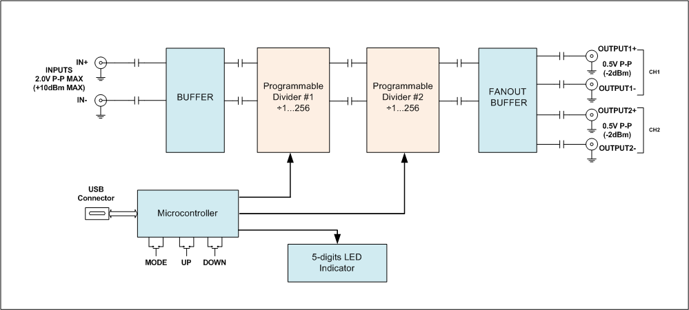
- Buffered differential input, which accepts the wide signal range from -6dBm to +10dBm
- Two low-noise programmable 1–256 frequency dividers connected sequentially
- The fan-out buffer with two differential outputs, which can be used as four single-ended outputs, delivering -2 dBm output signal level on each output
- USB-enabled microcontroller, which handles divider programming from the front panel and from the USB link.
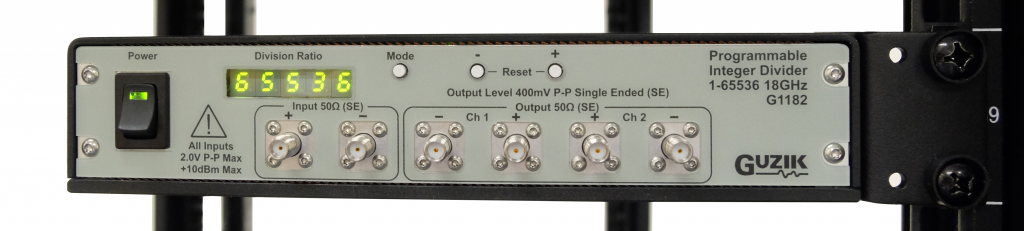
The division ratio is indicated on a 5-segment LED display on the front panel and can be controlled interactively by front panel buttons. The control of the divider can also be performed by the software application through the USB connection (useful for automated applications).
The duty cycle of output signal is 50% at any division ratio.
Because of the low phase noise, low jitter, and high SFDR the divider can be used in precision measurements in research and production environments.
For the best performance please terminate unused inputs and outputs with 50 Ohm termination.
The design requires a single +12V, 2A DC supply.
Programmable Frequency Divider
You can program the G1182 either interactively from the front panel, or programmatically through the USB link.
The USB software API is described in a separate document.
The front panel has 5-digit LED indicator and three control buttons: “Mode”, “+” and “–“.
The “Mode” button cyclically switches between three control modes:
- Full Divider ratio control
- Divider #1 ratio control
- Divider #2 ratio control
In the Full Divider ratio control mode you change the combined divider ratio of both dividers ranging from 1 to 65536. In this mode the LED indicator shows the combined divider ratio. This mode is selected by default on the power up.
Because two 1–256 dividers are connected sequentially, not all divider ratios in the 1–65536 range are possible to set. For example, if the divider ratio is divisible by a prime number greater than 256, such divider ratio is not possible to achieve. The microcontroller automatically skips ratios which are not possible to achieve.
In the Divider #1 and Divider #2 ratio control modes you change the divider ratio of an individual 1–256 divider: #1 or #2. In these modes the LED indicator shows the divider number (1 or 2) followed by dash, followed by the divider ratio or an individual divider.
For the best performance the microcontroller will not let you to select the divider #1 ratio smaller than the divider #2 ratio, or the divider #2 ratio greater than the divider #1 ratio. In a case of such attempt the LED indicator will show _ _ _ _ _ or ¯ ¯ ¯ ¯ ¯ respectively.
The “+” and “–” buttons increment and decrement the selected divider ratio. When “+” or “–” button is pressed once, the divider ratio changes to the next or previous available value. When pressed and held for more than a second, the divider ratio starts changing with slow speed. When you continue to hold a button, the divider ratio starts changing with faster speed.
When “+” and “–” buttons are pressed simultaneously they reset the selected divider to 1.
The selected divider ratio is automatically saved into the non-volatile memory and restored on the power up.
Specifications[1]
| Input | |||||
| Division Ratio 1 | Division Ratio ≥ 2 | ||||
| Frequency Range | 100 kHz – 16 GHz | 100 kHz – 18 GHz | |||
| Input Level | ≤ 15 GHz | -6…10 dBm 0.3…2V p-p |
≤ 17 GHz | -6…10 dBm 0.3…2V p-p |
|
| 15…16 GHz | 0…10 dBm 0.63…2V p-p |
17…18 GHz | 0…10 dBm 0.63…2V p-p |
||
| Input Impedance | 50 Ohm single-ended, 100 Ohm differential | ||||
| Return loss (typ.) | -8 dB at 15 GHz | ||||
| Divider Ratio | 1…65536[2] (achieved as a combination of two sequential 1–256 dividers) |
||||
| Output | |||||
| Output Level | 0.5V p-p single-ended | ||||
| Output Impedance | 50 Ohm single-ended | ||||
| Duty Cycle | 50 % | ||||
| Return Loss (typ.) | -10 dB at 15 GHz | ||||
| Rise/Fall Time (typ.) | ≤ 26 ps | ||||
| Noise Performance | |||||
| Phase Noise[3] (typ., see Figure 1) |
13.3 GHz input, ratio ÷1[4] | -110dBc at 1kHz offset | |||
| 13.3 GHz input, ratio ÷14 | -131dBc at 1kHz offset | ||||
| SFDR (typ., see Figure 2, Figure 3) |
≥ 75 dB | ||||
| Electrical and Mechanical | |||||
| Power Source | +12V, 2A DC | ||||
| Power Consumption | 9 W | ||||
| Dimensions | 8.3” (W) x 4.6” (D) x 1.66” (H) 211 mm (W) x 117 mm (D) x 42 mm (H) |
||||
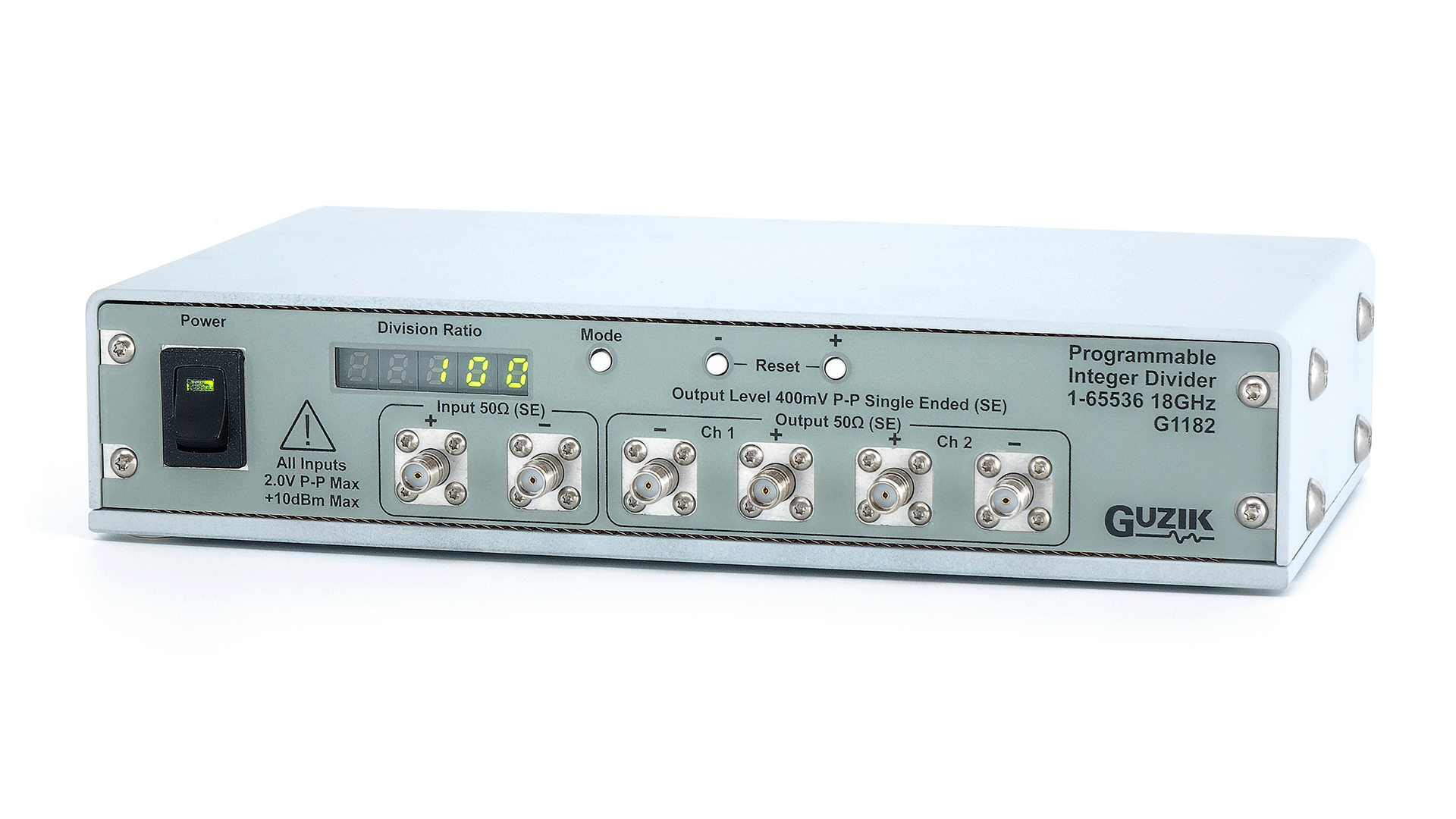
| Front Panel | Two input SMA jacks Four output SMA jacks Power switch with green LED ON indicator 5-digits LED division ratio indicator 3 control buttons |
||||
| Rear Panel | +12V DC input, (mating plug: outer diameter 5.5mm, center pin diameter 2mm)USB Type C connector |
||||
| Operating Environment | |||||
| Temperature Range | 0° to 50°C (32° to 122°F) | ||||
| Relative Humidity | 10 to 90% non-condensing | ||||
| Regulations | Designed to meet UL 60950, FCC Class B, CE safety and emissions | ||||
[1] Specifications are subject to change without notice
[2] Not all divider ratios are possible to set: if the ratio is divisible by a prime number > 256, such divider ratio is not achievable
[3] The phase noise increases for low slew rate input signals. It is recommended to use input signal with fast rise/fall time (≥ 4V/ns) for low frequency operations
[4] Limited by the signal source
Typical Phase Noise
13.3 GHz input signal, division ratios ÷1, ÷4, and ÷14
| Frequency offset, Hz | Phase Noise, dBc/Hz | ||
| ÷ 1 | ÷ 4 | ÷ 14 | |
| 10 Hz | -60 | -69 | -79 |
| 100 Hz | -86 | -96 | -108 |
| 1 kHz | -110 | -123 | -132 |
| 10 kHz | -112 | -124 | -134 |
| 100 kHz | -116 | -128 | -138 |
| 1 MHz | -138 | -145 | -150 |
| 10 MHz | -142 | -146 | -150 |
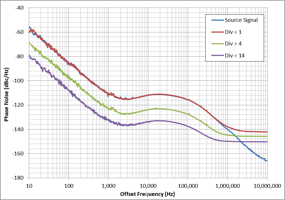
Figure 1
Typical SFDR
| 14 GHz input signal, div. ratio ÷2 | 18 GHz input signal, div. ratio ÷2 |
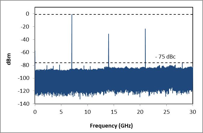 |
 |
| Figure 2 | Figure 3 |
Ordering InformationPlease contact sales@www.guzik.com to obtain a quotation for the: |
|
| Package Contents | |
| Item | Quantity |
| G1182 Programmable Integer Frequency Divider | 1 |
| 12 V power supply with 2 m (6 ft.) cable | 1 |
| USB type A to USB type C control cable, 2 m (6 ft.) | 1 |
| 50 Ohm SMA terminators | 6 |
| Ear for 1U half rack mounting (shown below) | optional |