Guzik MR7 Read/Write Headamplifier – Discontinued
- 3 GHz Low-Impedance Current Sense Read Amplifier
- 4 Gbit/sec Write Data Speed
- 100 psec Rise/Fall Time of Write Current
- Programmable Width and Amplitude of Overshoot
- Write-to-Read and Read-to-Write Recovery Time below 100 nsec
- Programmable Heater Control
- Microactuator Support
Guzik MR7 amplifier is designed for high-speed operation with RWA-2000 series. Compared with MR5 head amplifier, it has much wider bandwidth of write and read channels and significantly faster rise/fall time of write current. As a result, the MR7 can operate with data speed up to 4 Gbit/sec.
The output impedance of the MR7 write driver is 60 Ohm differential. The impedance can be changed per customer request to match a write-head specification. Since the read amplifier of the MR7 is a low-impedance current sense amplifier, the MR7 can work with both TMR and GMR types of magnetic heads.
MR7 Read/Write Amplifier Specifications:
Write Driver
Write data speed: up to 4Gbit/sec
Rise/fall time of write current (100% overshoot): 100 psec (10-90%)
Output common mode voltage: less than ±0.1 V
Write current: programmable 0 to 100 mA
(zero to peak)
Read-to-write recovery time: less than 100 nsec
Head voltage swing: more than 12 V peak to peak
Programmable overshoot:
- Amplitude 0 to 100 mA (zero to peak)*
- Width from 250 psec to 900 psec (PW50)
Output impedance: 60 Ohm differential (contact sales@www.guzik.com for customer-requested output impedance)
________________
* Write current should not exceed 100 mA (zero to peak) for any overshoot value.
Heater Driver
- Single-ended or differential output configurable on the board upon customer request
- Output voltage: from 0 to 12 V (peak to peak, typical, adjustable upon customer request)
- Accuracy of output voltage setting: ±10 mV
- Output current: up to 125 mA in 0.1 mA steps
- Accuracy of current measurements: ±0.2 mA
- Two types of heater voltage control:
Internal control (via 16 bit DAC) separate in the read and the write mode
External control (through MCX connector) with input range from 0 to 3 V and amplification 2 (typical, adjustable upon customer request)
- Heater impedance: 50 Ohm or higher
- Rise/Fall time: 100 nsec (defined by 4 MHz internal low-pass filter)
- Resistance measurements
Read Amplifier
Differential current sense low-impedance amplifier
Bandwidth: DC to 3GHz at –3 dB
- Flatness ±0.5 dB, 0.3 MHz to 2 GHz
- Group delay flatness ±50 psec to 2 GHz
Input noise:0 (typical)
MR bias voltage: programmable ±400 mV in 0.1 mV steps
MR Head Impedance: up to 1000 Ohm
MR impedance measurement accuracy: 1% within the bias voltage range (20 mV to 400 mV)
Common mode rejection ratio: 24 dB (typical) in full bandwidth (18 dB minimum at 700 MHz)
Non linear distortion (1 GHz, 1 mV input level): less than 1%
Amplification: 30 dB**
Write-to-read and read-to-write recovery time: 100 nsec (typical) for both Bias On and Shut Down Bias modes***
Input impedance: 80 Ohm differential (typical)
Guzik MR7 head amplifier compatibility: with Universal Preamplifier UP10 only.
________________
** Required amplification is provided by UP10.
*** Measurements conditions: write current 50 mA, head inductance 5 nH, write data 1 Gbit/sec.
Microactuator
Single-ended or differential output configurable on the board upon customer request
MR7 Write Driver Test Setup
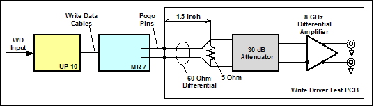
Write Current Waveform
Measurement Conditions: write current 50 mA, overshoot amplitude 100%, head equivalent 5 Ohm.
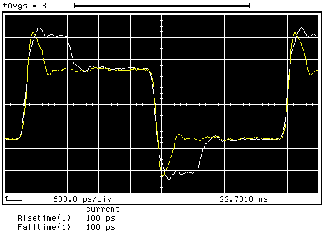
Figure 1: Write current with the minimum and the maximum overshoot width
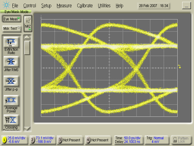
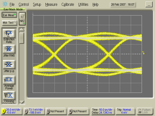
Figure 2: Write current eye diagram at 4 Gbit/sec, pattern PRBS 1+x8+x4+x3+x2,
100% overshoot, overshoot width 250 psec