
Signal Analyzers for Tektronix TDS 7000 Series Oscilloscopes – Obsolete
Jitter and Eye Diagram Analysis Package
The Jitter and Eye Diagram Analysis package delivers wide set of timing measurements, including measurements of signal period jitter, pulse width jitter, rise/fall times, time interval errors and skew/setup/hold times.
It supports different measurement result representations like eye diagram, histogram, jitter track/trend, jitter spectrum, and unique eye diagram slicing mode with the ability to select the signal area of interest directly on the eye diagram for further measurements (see Fig. 1).
The jitter measurement solution from Guzik Technical provides outstanding measurement accuracy of < 1ps RMS on TDS7404 oscilloscope.
- Comprehensive set of measurement including period, pulse width, rise/fall times, time interval error, skew/setup/hold times
- < 1 ps RMS measurement accuracy with Tektronix TDS7404 oscilloscope
- Eye diagram, histogram, track/trend, and spectrum representation of results
- Unique eye diagram hardware zoom capability for increasing resolution
- Digital Phased Lock Loop (PLL) with programmable bandwidth and digital clock recovery for precise time interval error measurements

Fig. 1. Jitter Histogram of Selected Part of Eye Diagram
(2.2ps RMS Jitter Measured)
Disk Drive Analysis Package
The industry leader in disk drive and magnetic head testing equipment, Guzik Technical Enterprises applied its extensive expertise to develop the comprehensive oscilloscope-based disk drive testing solution.
The Disk Drive Analysis package delivers wide range of industry standard measurements including Parametric, NLTS, SNR and Pulse Profile. It integrates a Digital PRML Channel with PR4, EPR4, E2PR4, and variable target PRML modes. It includes the extensive array of fully programmable digital filters/equalizers, digital clock and gain recovery with programmable bandwidth and customizable Viterbi decoder.
Disk Drive Analysis application provides automatic optimization of Digital PRML Channel, auto-setup of many software parameters, disk drive and oscilloscope triggers, measurement gating and much more.
- 8Gbit/s PRML channel analysis with Tektronix TDS7404 oscilloscope
- Digital PRML with PR4, EPR4, E2PR4, and Variable Target modes with automatic target optimization
- Industry-standard Disk Drive measurements including Parametric (TAA, PW, Asymmetry), NLTS, SNR and Pulse Profile
- Wide range of programmable digital filters
- Disk drive specific triggers and gating
Integration with Guzik Testers
The Disk Drive Analysis package provides integration with Guzik WITE32 software and can be used with Guzik RWA-2585 and RWA-2000 series. For example, the track profile measurement with error rate curve can be performed by Disk Drive package by analyzing the read data from a Guzik spinstand (see Fig. 2).
Fig. 2. Track Profile with Error Rate (Bathtub Curve)
(1Gbit/s Data Rate, Error Rate Better than 10-6)
Disk Drive Analysis Package Features
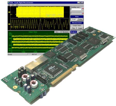
- Guzik Hardware Accelerator Card integrated with Tektronix oscilloscope provides real-time signal analysis and data processing
- 8Gbits/sec complete PRML channel analysis with Tektronix TDS7404
- Digital PRML with PR4, EPR4, E2PR4 and custom Variable Target modes with automatic PRML channel optimization
- Digital PRML measurements including Bit Error Rate, SAM, Sample Values Distribution
- Industry-standard Disk Drive measurements including Parametric (TAA, PW, Asymmetry), NLTS, SNR
- Unique Pulse Profile Parametric measurements with high noise immunity
- Wide range of programmable digital filters including low-pass and high-pass IIR filters and 32-tap FIR equalizer
- Drive-specific triggers and gating simplify and speed up your work
- Convenient and intuitive Windows-based User Interface optimized for touch-screen applications
- Integration with Guzik RWAs and Spinstands
Applications:
- Characterization of PRML channels in data storage and telecommunications
- Characterization and testing of magnetic heads and disk drives
- IDEMA measurements including TAA, PW50, SNR, Resolution and Asymmetry
Maximum Performance
Disk Drive Analysis package from Guzik Technical Enterprises delivers fast disk drive measurements on digital oscilloscopes. The package includes the Guzik Hardware Accelerator card and Guzik software environment installed on the Tektronix oscilloscope.
The 4 GHz analog bandwidth combined with 20 GSamples/sec sampling rate of Tektronix TDS7404 oscilloscope makes possible to perform PRML channel analysis up to 8Gbit/sec.
The unique design and strategic location of Guzik Hardware Accelerator card gives possibility to perform most time-critical measurements by hardware and in real-time with the speed of the oscilloscope acquisition.
Highly optimized Guzik graphical engine is capable to display large amounts of graphical data without slowing down the system.
Versatility
The Disk Drive Analysis package delivers wide range of disk drive oriented measurements including Parametric, NLTS, SNR and Pulse Profile. It integrates a highly flexible Digital PRML Channel with PR4, EPR4, E2PR4, and variable target PRML modes. The heart of the PRML channel is the digital clock and gain recovery with programmable bandwidth and customizable Viterbi decoder. The PRML channel also includes a wide range of programmable digital filters like low-pass and high-pass IIR filters and 32-tap FIR equalizer.
Disk Drive Analysis application provides semi-automatic optimization of Digital PRML Channel, auto-setup of product parameters, disk drive specific oscilloscope triggers and measurement gating.
Fig.1. Sample Values Plot, EPR4
Fig. 2. PRML Channel Optimization,
(Pulse Profile Capture and Reshaping)
Fig. 3. Sample Values Distribution Plot, EPR4
PRML Measurements
The Disk Drive Analysis package supports the wide range of PRML measurements and PRML channel performance evaluation tools:
- Semi-automatic PRML channel optimization procedure, which includes the isolated pulse shape capture, pulse reshaping and equalizer adjustment (see Fig. 2).
- Sample Values plot to display PRML samples at the output of the clock recovery over the time (see Fig.1).
- Sample Values Distribution plot with MSE calculation to display the synchronized histograms of PRML samples (see Fig.3).
- Comparator Error plot with BER calculation to display recovered user data along with reference data in NRZ format.
- SAM Data plot to display Viterbi metric margins over the time.
- SAM Histogram plot to display the histogram of Viterbi margins.
- SAM Plot with SAM BER calculation to display the margins distribution.
- TAA and Error Rate Track Profile (Bathtub Curve). Guzik RWA and spinstand is required for this test.
Easy to Use
The Disk Drive Analysis package provides intuitive Windows-based GUI optimized for oscilloscope touch-screen. For added convenience it supports second external monitor and front-panel oscilloscope knobs.
Digital Oscilloscopes Supported
| Oscilloscope Model | Platform | |
|
Guzik DSP Hardware
Accelerator |
Oscilloscope Sampling
Rate |
|
|
Tektronix TDS7104
|
10GS/sec
|
|
|
Tektronix TDS7154
|
20GS/sec
|
|
|
Tektronix TDS7254
|
20GS/sec
|
|
|
Tektronix TDS7404
|
20GS/sec
|
|
Specifications
| PRML Max Bit Rate | TDS7104: 2Gbit/sec TDS7154: 3Gbit/sec TDS7254: 5Gbit/sec TDS7404: 8Gbit/sec |
||||||||
| Acquisition Length | Up to 32 MSamples* | ||||||||
| PRML Modes | Variable Target, PR4, EPR4, E2PR4 | ||||||||
| PRML Measurements | Sample Values Plot, Sample Values Distribution Plot, MSE, Comparator Error Plot, Bit Error Rate (BER), SAM Data Plot, SAM Histogram Plot, SAM BER |
||||||||
| PRML Channel Optimization | Automatic and semiautomatic based on signal quality monitor | ||||||||
| Parametric Measurements | TAA, TAA+, TAA-, TAA Asymmetry, TAA Resolution, PW, PW+, PW-, PW Asymmetry, RMS |
||||||||
| SNR Measurements | Autocorrelation SNR, TAA/RMS (Guzik) SNR, RMS/RMS SNR |
||||||||
| NLTS Measurements | NLTS Dipulse Extraction, NLTS Autocorrelation |
||||||||
| Pulse Profile | Noise suppression up to 15dB SNR Repetitive patterns required |
||||||||
| Track Profile | Combined TAA profile and Error Rate profile (Guzik RWA and Spinstand required) |
||||||||
| Acquisition Trigger | Manual, Sector, Read Gate, Custom modes |
||||||||
| Measurement Gating | Manual, By oscilloscope cursors, By external Read Gate |
||||||||
| Parametric Measurements Accuracy (For Repetitive Patterns) |
|
* Limited only by oscilloscope’s available record length and current channel configuration, up to 32MSamples on Tektronix TDS7404.
Jitter and Eye Diagram Analysis Package Features
- Guzik Hardware Accelerator Card integrated with Tektronix oscilloscope provides fast signal analysis and data processing
- Measurement accuracy down to 1 psec RMS (with TDS7404 oscilloscope), which does not depend from oscilloscope trigger jitter
- Measurement of all main timing parameters of signals: period, pulse width, rise/fall times, time interval error (TIE), skew/setup/hold times
- Representation of all measured parameters in various graphical forms (histogram, track, trend, frequency domain) and in form of accumulated statistical results
- Eye diagram form of signal representation with powerful hardware zoom feature
- Internal clock recovery based on digital PLL with programmable bandwidth
- Capability of measurements at any distance and duration from user-defined reference event
- Jitter measurement of single input signal or channel-to-channel
- All measurements can be done using one acquisition or multiple acquisitions
- Comprehensive autoset feature simplifies product configuration
- Convenient and intuitive Windows-based User Interface optimized for touch-screen applications
| Applications:
Digital circuits design:
Telecommunication:
|
| Maximum Performance The Jitter and Eye Diagram Analysis package from Guzik Technical Enterprises delivers wide range of fast and accurate measurements of different timing parameters on digital oscilloscopes. The package includes the Guzik Hardware Accelerator card and Guzik software environment installed on the Tektronix oscilloscope. The 4 GHz analog bandwidth and 20 GSamples/sec sampling rate of Tektronix TDS7404 oscilloscope combined with sophisticated signal processing algorithms make possible to obtain measurement accuracy down to 1 psec RMS. The unique design and strategic location of Guzik Hardware Accelerator card gives possibility to perform most computation-consuming measurements by hardware, thus delivering high speed of operation.
Better by Design
The following benefits are resulted from the implementation of these principles:
Easy to Use Digital Oscilloscopes Supported
Specifications
* Limited only by oscilloscope’s available record length and current channel configuration |
||||||||||||||||||||||||||||||||||||||||||||||||||||