
Parametric TFC Control
Dynamic adjustment of write-mode TFC power, depending on four parameters:
- Write current
- Write current overshoot amplitude
- Write current overshoot duration
- Write signal frequency
Works transparently with WITE32, Guzik test modules, and WDK-based custom modules
Calculates write signal frequency depending on a data pattern, not just write clock
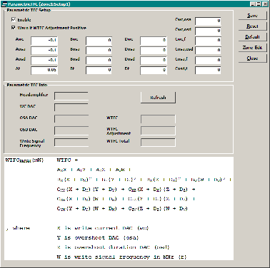
Parametric TFC allows for adjusting the value of the write-mode TFC power, in milli‑watts, depending on write-related parameters.
Every time any of these parameters change, the adjustment is calculated, and the total write-mode TFC, WTFCPARAM, which is a sum of a fixed write TFC value and TFC adjustment, is programmed into the headamplifier. Thus, the adjustment applies to all write and erase operations without intervention from the user.
The function describing the total write-mode TFC is given below:
WTFCPARAM(mW) = WTFC +
AXX + AYY + AZZ + AWW +
BX(X + DX)2 + BY(Y + DY)2 + BZ(Z + DZ)2 + BW(W + DW)2 +
CXY(X + DX)(Y + DY) + CXZ(X + DX)(Z + DZ) +
CXW(X + DX)(W + DW) + CYZ(Y + DY)(Z + DZ) +
CYW(Y + DY)(W + DW) + CZW(Z + DZ)(W + DW)
where
WTFC is a fixed TFC value
X is write current DAC (WC)
Y is overshoot DAC (OSA)
Z is overshoot duration DAC (OSD)
W is write signal frequency in MHz (F)
Write signal frequency FWR is calculated as FWR = FCLK / (2 * R), where FCLK is the write clock, and R is the average number of bit cells between two consecutive flux transitions. For writing through the PRML chip R = 2.
- WITE32 software revision 4.20 or later
- UP8 or UP10 universal preamplifier
- Commercial headamplifier with a driver, which supports programming TFC in milli‑watts
- Software License. Please contact sales@www.guzik.com to obtain a quotation for the license. Please provide the RWA EEPROM Dump with your request.